
When I visited the Velocity Factory for my demonstration ride, one of the items that I requested while airborne was to test out the diesel truck heater (designed to heat the cab of a semi). Scott couldn’t get it to start. After fiddling with it when we got back on the ground, he finally got it to turn on.
When I started building my airplane at the factory, we tried again. It would not turn on while airborne. We flew in another customer’s twin. It wouldn’t turn on either. Well, sometimes it would. It was quite finicky.
With twins it’s much harder to heat the cabin. The typical single engine airplane approach of a heater muff doesn’t work well. And it’s even more of a problem in a pusher configuration as the distance is just too far.
While the idea of installing a diesel truck heater in the twin was actually quite creative. I think the problem is that it isn’t designed to have so much air flow past the inlet and outlet air ports during flight. However, I know of one customer tweaked his to work pretty well, and he is satisfied with his heater.
In any case, I began to look for an alternative way to heat the airplane. This is challenging for a DC powered setup. It’s even more difficult if operating at 12 volts, rather than 24 volts. The combination of using electric heat, as well as, electric air conditioning pushed me to opt for a 24 volt airplane.
24 volts used to be less than ideal in an experimental airplane as it was much cheaper to go with 12 volt parts, particularly from the automotive world. However, these days, pretty much all the modern avionics operate with a range of about 10 to 30 volts.
Anyway, I spent a good deal of time looking for a suitable electrical heating solution. Velocity had no solutions at the time, but not for lack of trying to help. One person even cautioned me not to “burn up” my airplane. Hmm. What about a diesel heater in the nose compartment? Not worried about a fire there? Of course you are. The fact is that either solution has inherent risks.
I did find a company with some promising heaters – DC Thermal. I didn’t realize at the time, but they aren’t keen on selling into the world of aviation. No matter, as they do sell their products thru Aircraft Spruce! Go figure.
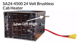
These are the heater specs:
Heater Dimensions: 6”x 5” X 4”
Brushless 50,000 Hour Ball Bearing Fan
10,000 Hour DC Thermal ™RuCar Vacuum Sealed Elements
Case Construction: Riveted T5052 Aircraft Aluminum
Wired Entirely with GXL Wire
Thermally Protected
HIGH and LOW HEAT Settings
Comes complete with mounting hardware, mounting bracket, fuse, fuse holder, electrical connector ends, and detailed instruction
_________________________________
One feature that helped me decide to go with these heaters is their internal thermal fuse. That should help avoid anything getting too hot as this fuse literally melts and that removes power to the elements.
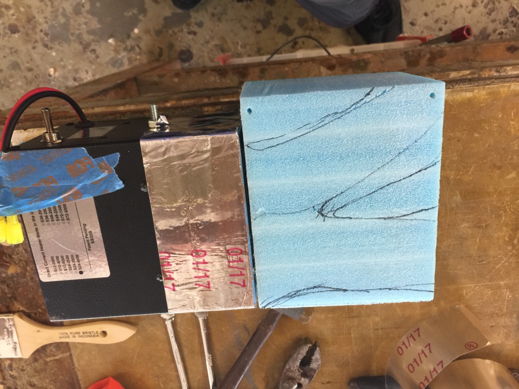
So I purchased a 24 volt heater rated at 45 amps, model SA24-4500. This was their highest output for a 24 volt heater. Then I began trying to design a solution around this heater.
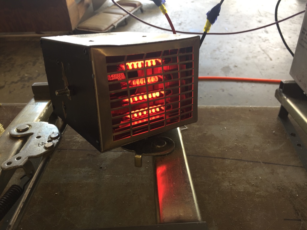
I began testing these heaters. How much air flow. How hot did the cases get, etc. There is a High/Low switch. The Low position only energized 2 of the 4 heating elements. This drops the amperage draw about in half.
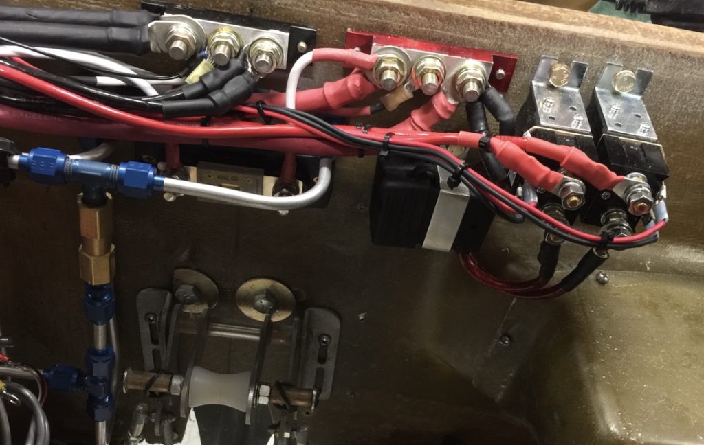
At first, I thought I would put the heater in the nose compartment, then split the output air and duct one side to the pilot’s feet and the other to the copilot’s feet. This turned out be quite challenging due to space constraints. Along the way, I had also ordered a built in oxygen system, and I had to figure out where to put the bottle. In addition, I had found some lighter weight alternators from Plane Power that would output 150 amps each in my 24 volt airplane. They claim 130 amps at 1,000 rpm! More than enough electricity.
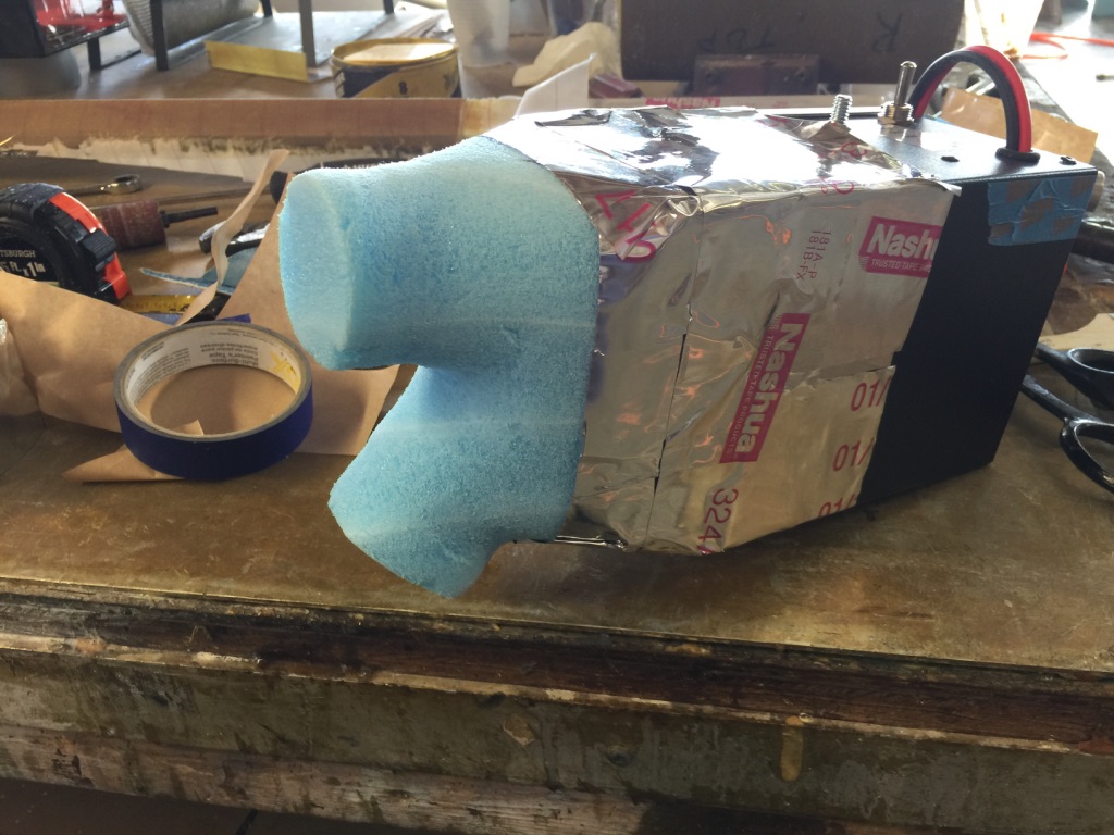
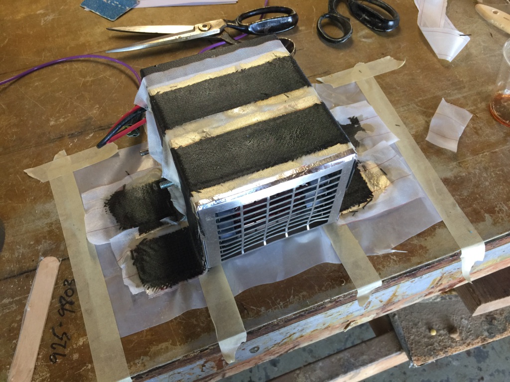
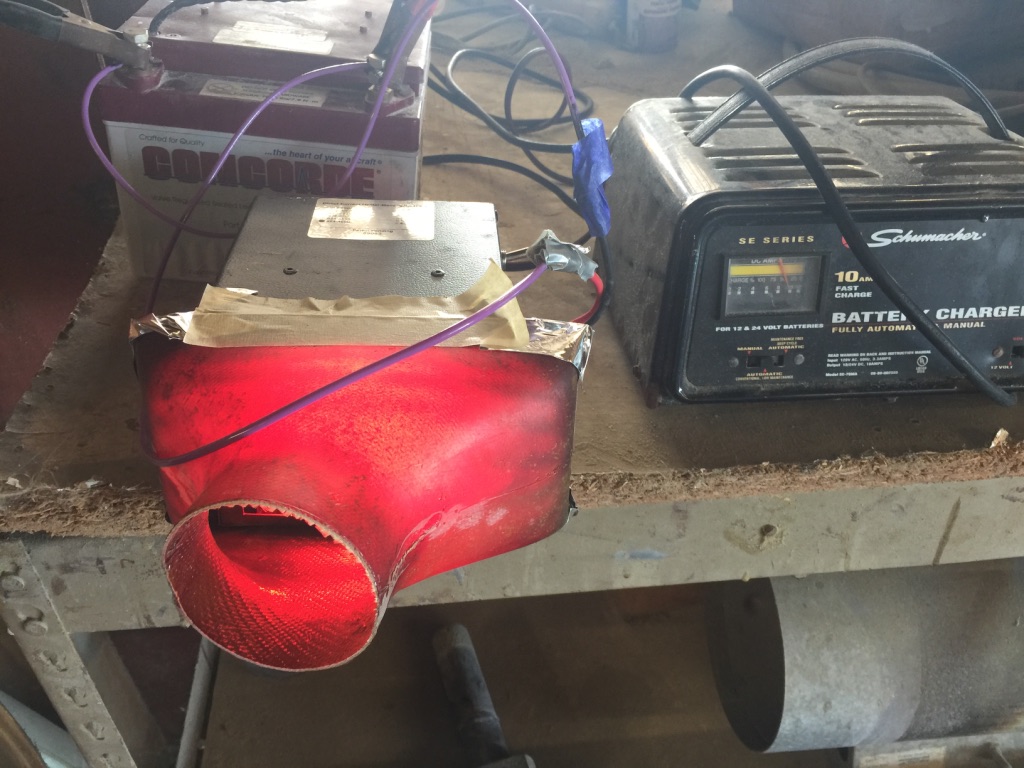
So I began the project by making a split duct. But after testing it, I decided there wasn’t enough airflow. I appeared that the amount of air output, once the air was “split”, would not get the job done. Now, as Velocity didn’t have a 24 volt power supply, they suggested I make a test rig/hookup to their golf cart batteries, which I did. I would characterize the output air as somewhat like a car fan on Low. Not that good.
Not using the diesel truck heater did open up some space in the nose compartment. In the end I chose to put the oxygen bottle in that spot, and rather than split the output from one heater, I purchased a second. The plan then became one heater for the pilot, and one for the copilot. I have owned airplanes with ineffective heating systems. I was determined to have a comfortable airplane. So it was two heaters, not one.
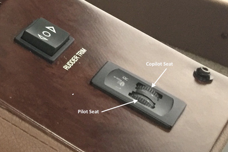
However, once I installed them in the airplane, and they were powered by my hefty 24 volt system, it turns out that the output air is more substantial. The golf cart batteries, for whatever reason, just didn’t result in much air flow. So powered by my Plane Power alternators, I would say the flow is more akin to a car fan on Medium or Medium-High. So pretty good. In any case, using two heaters worked out even better, as I also installed two separate digital controllers, one for each side. The temp sensors are placed at the bottom of the instrument panel on the respective side near the center console. His and hers. 🙂 I like it.
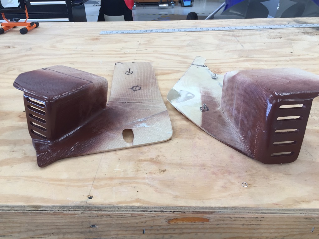
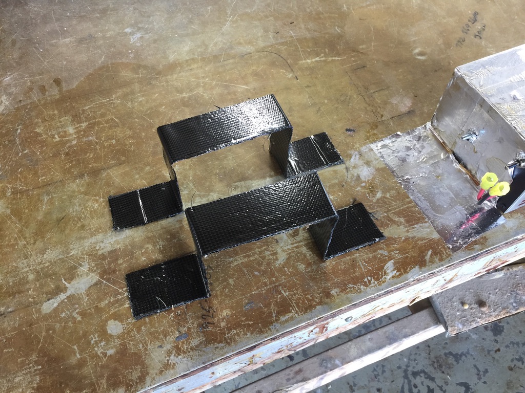
These are Fiberglas foot well and heater covers. I painted the inlet “grills” with a matching (to the other interior items) Imron epoxy paint. The rest of these panels are upholstered in Ultraleather as you will see in a subsequent photo.
Still, finding a suitable location was a challenge. I ended up placing them just below the side stick mounts just forward and below of one’s knee. After a lot of testing, it was the best place I could find. Scott Swing looked at these locations, and also considered the options, interference with other items, etc. He then gave it his “blessing”.
Also, in designing this system, Scott assured me that the basic interior air flow in the airplane is from front to back. He is confident that if the front seat passengers are comfortable, the back seat passengers will be just fine, as well.
Ideally, I would like heaters that function like these do (quite well), but that have a flatter form factor. Their “boxy” design makes locating them a challenge.
Bryan, at Velocity, has now found another company that makes similar heaters. They are the same size in depth (bummer) but they are 1″ inch smaller in length.
Every bit helps, though. I might consider upgrading to them at some point.
In the meantime, I am actually quite satisfied with these heaters and where I put them. They do keep us nice and warm.
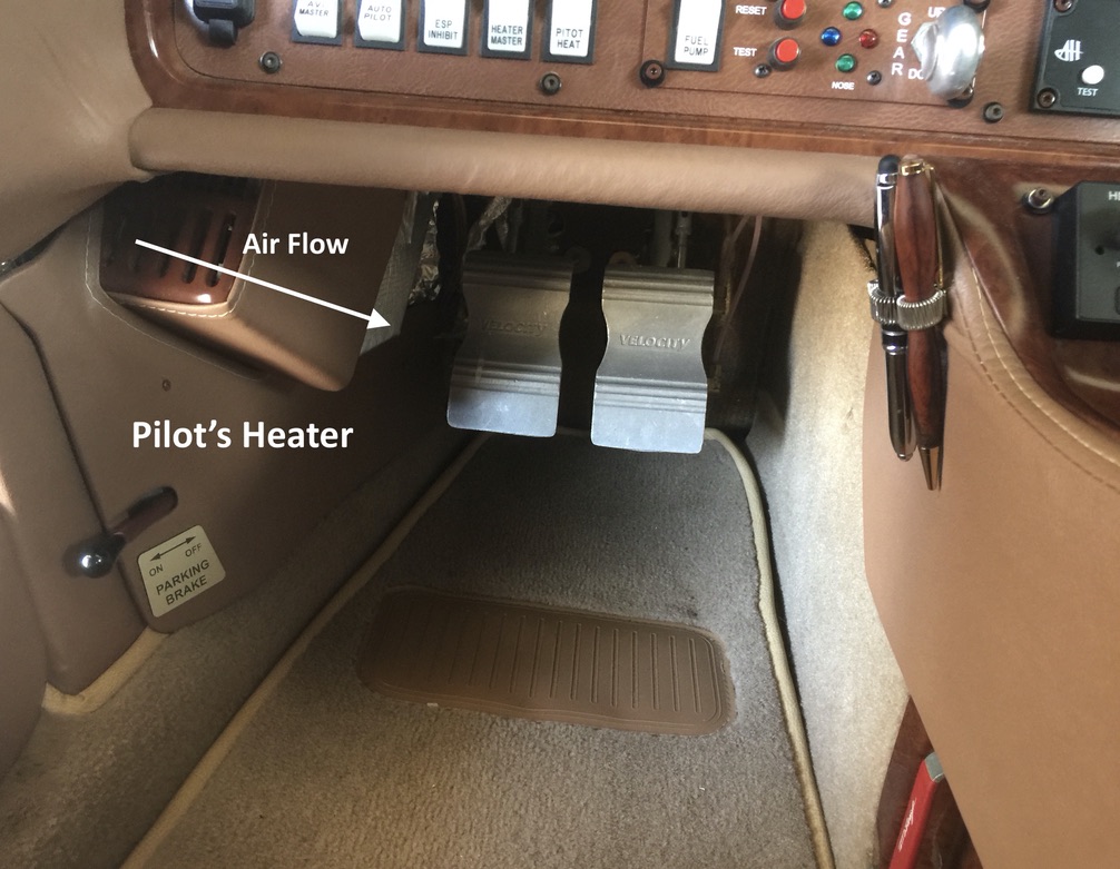
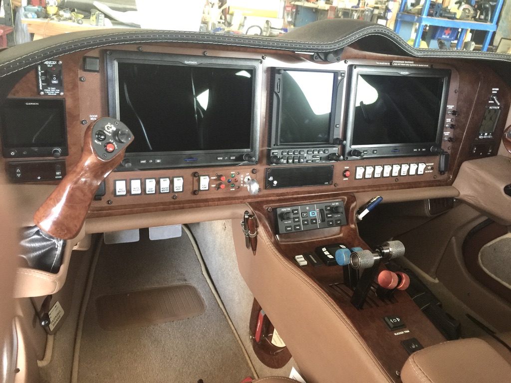
On the left, you can see where the pilot heater is installed. It has the custom Fiberglas panel over it, and is covered in Ultraleather. For a photo taken more at eye level, look at the right side. There you can just see the copilot’s heater tucked away quite nicely. They don’t interfere with leg room at all. They are mounted in the just the “right” spot. 🙂
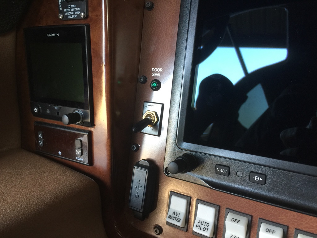
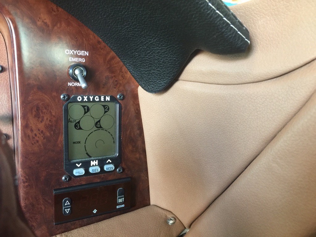
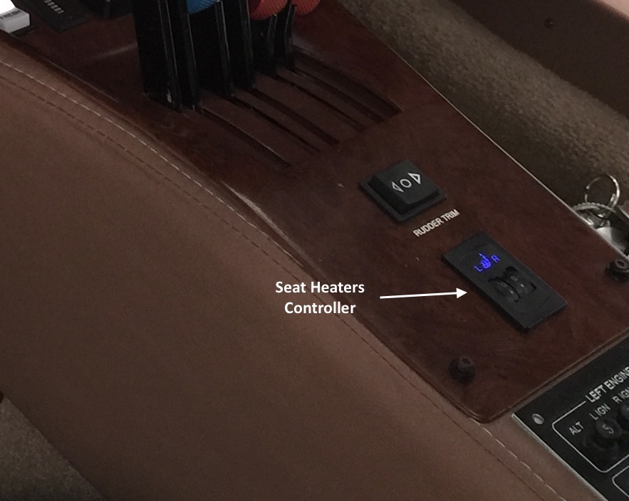
On the left, you can see the pilot’s side digital controller, just below the G5 backup EFIS. On the right, you can see the copilot’s side digital controller, just below the oxygen system controller.